
Case study: Diehl Controls
Increase strength of 3D printed parts is often limited by anisotropy in FFF printing—especially along layer lines. This case study shows how splitting the model and optimizing orientation improved multi-axis durability for a Diehl Controls component, without significantly changing total print time.
Source note: This article is based on an internal Omni3D case study performed by a 3D Printing Specialist using Omni3D equipment and verified print parameters.
Summary
Diehl Controls required a 3D printed part with high mechanical strength in multiple directions. Printing the part as a single piece using a standard approach proved insufficient: based on the information provided, the part was prone to cracking into multiple pieces if dropped or mishandled.
To address this, the model was split into smaller sections, each printed in an orientation selected to reduce weakness at critical zones. After printing, the parts were assembled using an engineering adhesive, improving strength in previously identified weak points while keeping total print time largely unchanged.
Increase strength of 3D printed parts: the anisotropy problem in FFF printing
FFF/FDM parts are naturally anisotropic. That means strength can vary depending on direction: a part may be strong in one axis but weaker along layer lines in another.
This becomes a practical problem when a component:
- experiences impacts (drops, knocks),
- has thin areas or small cross-sections, or
- must withstand loads from multiple directions.
In this project, the failure risk was linked to weak zones created along layer lines in areas with limited cross-sectional surface.
Identify weak points before changing the process
Step 1: Choose an orientation that balances supports and overall strength
The first step was selecting an orientation that offered the best balance between:
- minimizing support structures, and
- maximizing overall part strength.
Printing the model upside down was considered, but it would require more support structures, increasing both material usage and print time.
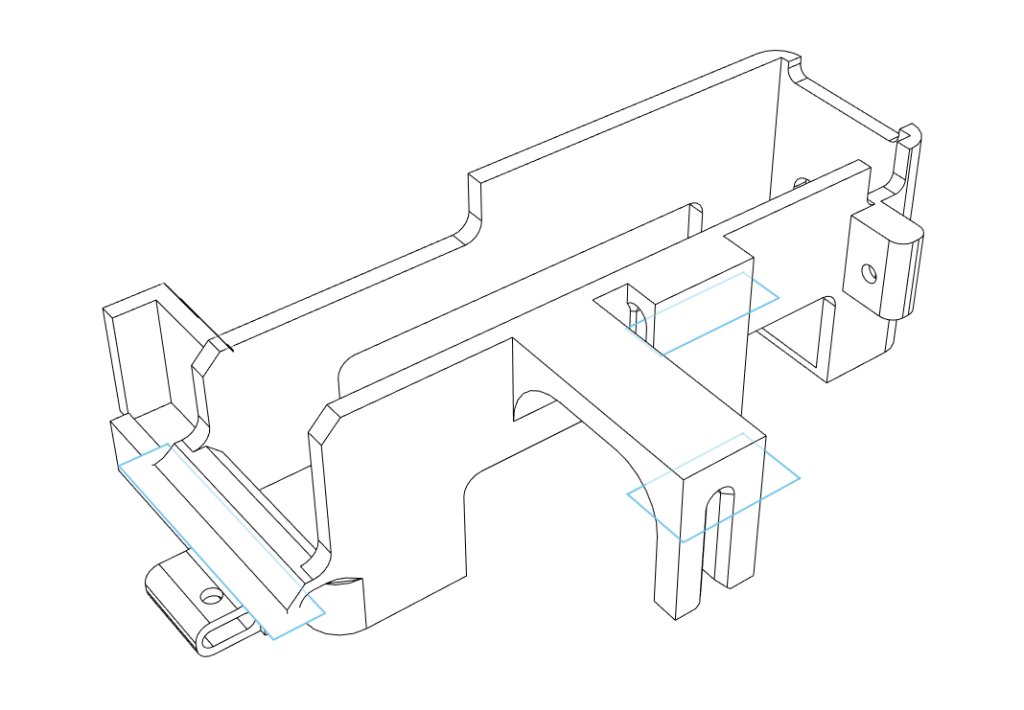
Step 2: Locate layer-line weakness zones
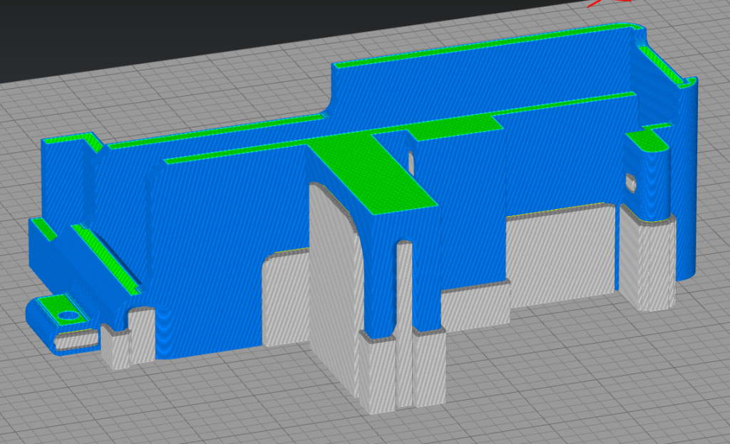
Even the most “reasonable” single-piece orientation can introduce weakness:
- along layer lines,
- in areas with small cross-sectional surface.
These zones were treated as likely failure points and became the primary targets for improvement.
Increase strength of 3D printed parts by splitting the model
Instead of printing the entire model as one part, the component was divided into smaller parts and printed separately.
Why splitting works (in this case)
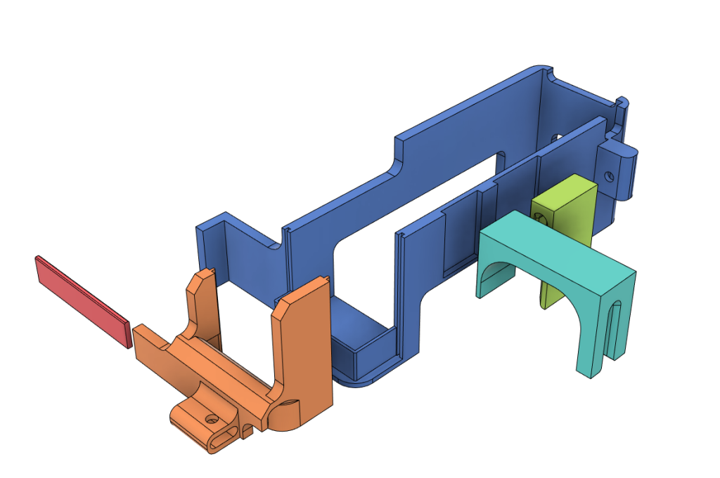
Splitting allowed each section to be printed in an orientation optimized for strength in its critical regions—without being forced into one global compromise.
A key requirement at this stage was designing:
- reliable joints and interfaces, and
- correct tolerances to ensure accurate assembly after printing.
Printing and assembly (technical details)
Printing setup
All parts were printed on an Omni TECH using:
- Kimya ABS ESD (as required by the application),
- HIPS-20 support material.
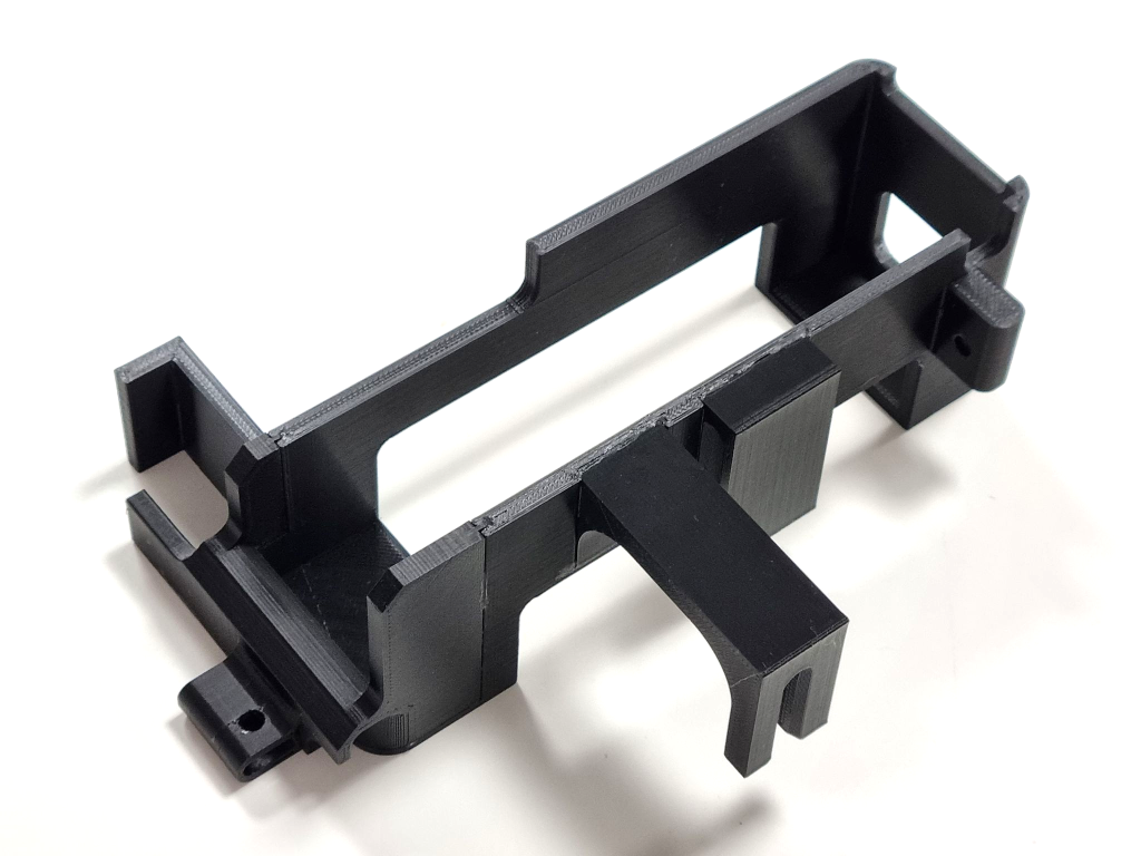
Assembly
After removing the supports, the final component was assembled using:
- ARALDITE® 2000 engineering adhesive.
Results
During testing, the assembled model showed increased strength in previously identified weak points, while total print time was largely unchanged.
Measured outputs
- Total print time: 10:50 hours
- Final part weight: 109.12 g (supports not included)
Technical summary table
| Item | Value |
|---|---|
| Printer | Omni TECH |
| Main material | Kimya ABS ESD |
| Support material | HIPS-20 |
| Assembly adhesive | ARALDITE® 2000 |
| Total print time | 10:50 h |
| Part weight | 109.12 g (supports not included) |
Practical takeaways
- If your part fails along layer lines or in thin/small cross-section regions, splitting the model can be a practical way to increase mechanical robustness.
- Splitting makes it possible to optimize orientation per section, reducing the “one-orientation compromise.”
- Successful assembly depends on well-designed interfaces (joints and tolerances) and a suitable engineering adhesive.
FAQ
How to increase strength of 3D printed parts without changing the material?
Start by identifying the likely failure zones (often layer lines in small cross-section areas). If orientation alone creates a tradeoff between strength and supports, splitting the model into sections can allow orientation optimization per section without a single global compromise.
Why did the original one-piece print crack easily?
FFF/FDM parts are anisotropic: strength varies by direction, and weak zones can form along layer lines—especially where the model has a small cross-sectional surface.
Why not just change the orientation instead of splitting the part?
An alternative orientation was possible, but it required more support structures, increasing material usage and print time. Splitting enabled independent optimization of each section’s orientation.
What materials and equipment were used?
The parts were printed on Omni TECH using Kimya ABS ESD with HIPS-20 supports, then assembled with ARALDITE® 2000.
Did splitting increase print time?
Total print time was largely unchanged. The complete print took 10:50 hours, and the final part weight was 109.12 g excluding supports.
About the author

Bartosz Liberski
3D Printing Specialist
bl@omni3d.net