Industrial 3D printing tooling can significantly reduce the time, component count, and material required to produce custom jigs, fixtures, and production-line assemblies. In this case study, a Tier-1 bearing manufacturer redesigned a 24-part CNC-machined tooling system for dual-material industrial FFF, reducing it to 12 components and shortening fabrication from 8–10 weeks to just one week.
When a custom production assembly requires multiple interconnected parts, conventional machining constraints often force design engineers to split complex shapes into numerous individual pieces. This design approach increases the total assembly part count, adds unnecessary mass to the automation line, and introduces multiple failure points.
By shifting to industrial-grade large-format additive manufacturing, specifically via open-material Fused Filament Fabrication (FFF), enterprise operations can dramatically consolidate part counts, lower structural weight, and compress multi-week fabrication backlogs into days.
The Engineering Challenge: Part Complexity and Bloated Lead Times
Traditional subtractive manufacturing requires specialized tool access paths, which restricts geometric freedom. When a global Tier-1 bearing manufacturer evaluated the transportation tooling system inside an automated assembly machine, they faced standard production challenges:
- Excessive Components: The original CNC-machined tool assembly consisted of 24 individual parts, requiring intensive manual assembly and alignment.
- Material Inefficiency: The structural setup consumed 2.5 kg of material per set, increasing the mechanical payload on robotic handling arms.
- Extended Lead Times: Procurement, machining setup, and final fabrication required 8 to 10 weeks for a single replacement run, creating an unacceptable maintenance risk.
To eliminate this supply chain friction, the tool design team restructured the component geometry specifically for industrial FFF 3D printing.
The Solution: Material Optimization and Soluble Support Systems
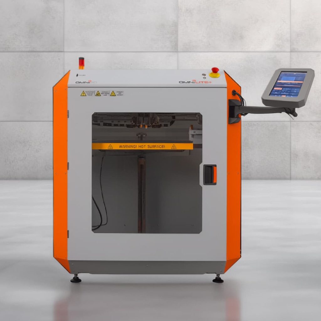
By transitioning from a physical tooling inventory to a validated digital inventory and industrial additive manufacturing platform with a controlled, actively heated chamber, engineers optimized the tooling geometry across three distinct phases:
1. Geometric Optimization and Part Consolidation
The tooling design was structurally audited to reduce the total number of components and simplify the downstream assembly process. Complex tracking channels that previously required separate machined blocks were integrated directly into a singular, unified digital model.
2. Dual-Material Co-Extrusion with Soluble Support
To fabricate complex internal channels without sacrificing surface accuracy or dimensional stability, a dual-extrusion system was deployed. The primary structural body was printed using a high-grade ABS engineering thermoplastic. To support the complex internal overhangs and bridges, an alkaline-soluble support material (ODS-20) was simultaneously extruded.
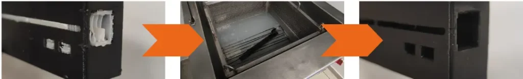
Complex internal channels and enclosed geometries can be produced using ODS-20 soluble support material, which is removed after printing with a mild alkaline solution.
[Dual Extruder Array]
├── Extruder 1: ABS Engineering Thermoplastic (Structural Body)
└── Extruder 2: ODS-20 Soluble Filament (Internal Scaffolding)
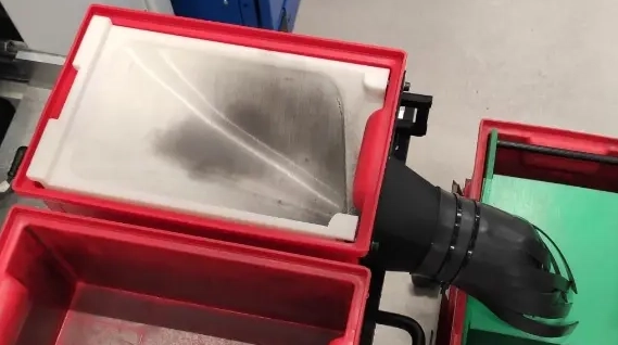
Post-printing, the entire assembly was placed into a specialized ultrasonic bath. The support scaffolding completely dissolved, leaving a clean, highly precise internal geometry that would be impossible to replicate via standard CNC milling.
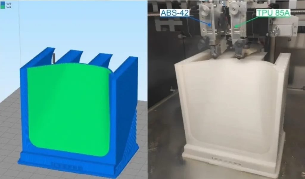
A similar application of dual-material industrial 3D printing helped BOSCH validate a complex production tray using ABS-42 and soluble ODS-20 support.
3. Hardened Mechanical Testing
The consolidated additive assemblies underwent rigorous stress testing on the factory floor to verify that their mechanical durability, layer adhesion, and wear resistance matched the performance of legacy subtractive tooling.
The Real-World Impact: Subtractive Machining vs. Additive Tooling
The operational shift from traditional subtractive machining to large-format industrial FFF printing yielded immediate, quantifiable improvements across every key performance indicator:
| Operational Metric | Legacy CNC Subtractive Methods | Industrial FFF Additive Manufacturing | Total Optimization Impact |
| Assembly Part Count | 24 separate components | 12 unified components | 50% Reduction in parts |
| Material Weight | 2.5 kg per tooling set | 2.0 kg per tooling set | 20% Mass Reduction |
| Fabrication Lead Time | 8 to 10 weeks | 1 week | 90% Faster Turnaround |
Traditional CNC ──► 8-10 Weeks
Industrial FFF ──► 1 Week (90% Lead Time Reduction)
Beyond compressing turnaround times, the mass reduction from 2.5 kg to 2.0 kg significantly minimized material usage and reduced wear on the system’s automated drive motors.
Industrial additive manufacturing can also support metrology and inspection through 3D printed quality-control fixtures produced more quickly and economically than conventional tooling.
Eliminating Line Downtime with Multi-Material Tooling Assemblies
Another strategic advantage of industrial-grade 3D printing on the factory floor is the ability to co-extrude distinct mechanical properties within a single print cycle.
On high-speed automated lines, components are frequently exposed to repetitive impact shock. For instance, sorting systems that direct heavy metal parts into collection bins face constant wear and tear. Standard rigid steel components lack dampening capabilities, leading to component damage and unexpected line stoppages for maintenance.
[Unified Print Cycle] ──► Structural Base: Durable ABS Thermoplastic
──► Internal Contact Slide: Shock-Absorbent TPU (85A)
By leveraging dual-material industrial printing, engineers can combine a rigid structural backing (like ABS) with localized, flexible dampening pads (such as a shock-absorbent TPU 85A elastomeric insert) in one continuous build operation.
This specific material combination ensures that the structural base maintains strict dimensional accuracy, while the elastomeric contact zones absorb continuous kinetic energy. On active industrial production lines, implementing multi-material additive components has successfully eliminated over 50 hours of mechanical system downtime per installation.
Open Platform Economics: Maximizing Factory Floor ROI
When scaling additive manufacturing across enterprise maintenance, repair, and operations (MRO) networks, total cost of ownership (TCO) is a critical factor. Many early adopters face high operating costs due to closed-source hardware platforms that require proprietary, chipped material cartridges.
Proprietary Closed Filament TCO ──► €115 – €125/kg
Industrial Open Platform FFF TCO ──► €40/kg (Up to 68% Cost Savings)
Selecting an industrial printer engineered around a validated, open-material platform allows production facilities to source engineering-grade polymers directly from global chemical innovators (such as BASF, DuPont, or Mitsubishi).
This open architecture delivers clear financial benefits:
- Reduced Consumable Costs: Standard industrial ABS filaments on open systems average roughly €40 per kilogram, compared to €115 to €125 per kilogram for identical materials locked behind proprietary ecosystems.
- Advanced Structural Properties: High-stress applications can utilize chopped carbon fiber matrices (such as CF-PA12) inside actively heated processing chambers to print high-stiffness components that successfully replace traditional metals, without paying closed-source premiums.
Summary: Building a Resilient Digital Inventory
Transitioning from physical, slow-moving replacement part storage to a localized digital inventory allows manufacturing plants to insulate themselves from supply chain shocks. By maintaining verified CAD designs for custom tooling, alignment jigs, and line fixtures, operations teams can print high-durability components on demand right on the factory floor.
Consolidating part assemblies, utilizing dual-material dampening profiles, and choosing open industrial hardware architectures allows modern production facilities to lower material usage by 20%, eliminate assembly friction, and cut tooling lead times by 90%