
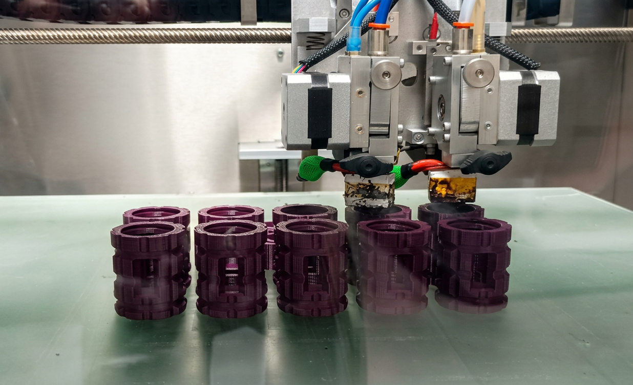
As Omni3D prepares for IMTS 2026, September 14–19 at McCormick Place in Chicago, we are bringing a practical question to the conversation: how can manufacturers make small-series additive production more efficient? From functional tooling to selected end-use parts, the opportunity is to connect printing capability with the cost, throughput and quality requirements of the shop floor.
Reducing additive manufacturing cost per part requires a coordinated approach to deposition rate, support strategy, finishing and quality control. For small-series production, the useful measure of throughput is the number of accepted parts delivered within a defined period, with all production stages included.
For jigs, fixtures, robotic end-effectors and selected end-use components, fused filament fabrication (FFF), a material extrusion process, offers a route to producing complex geometries without dedicated molding tools. The business case depends on whether the complete workflow meets the required cost, delivery date and acceptance criteria.
Bridge production uses this capacity to supply parts while a longer-term manufacturing route is being prepared. Small-series production can also remain additive throughout the product lifecycle. Both approaches require a repeatable process and a realistic capacity model.
Start with Additive Manufacturing Cost per Part
A useful batch-level calculation is:
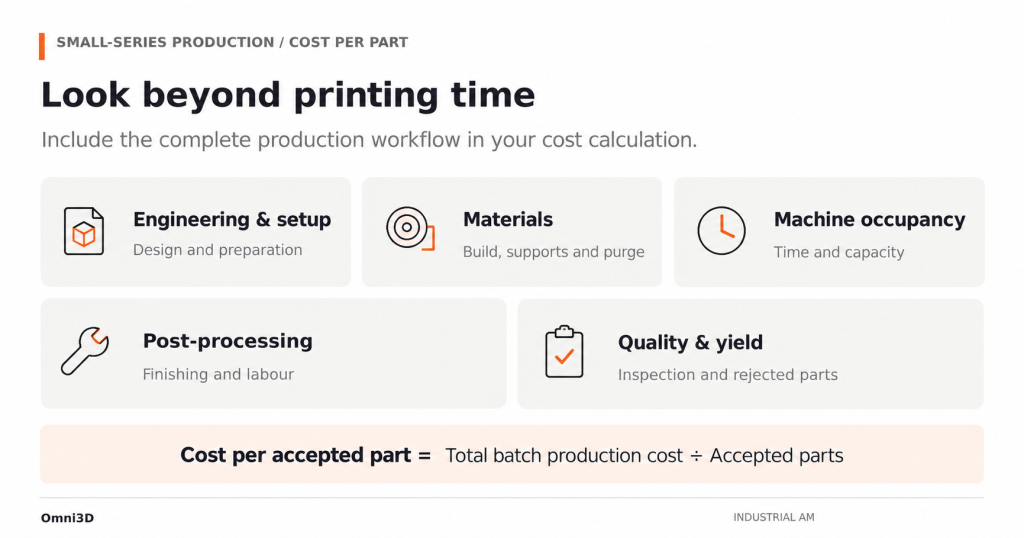
Cost per accepted part = total batch production cost ÷ number of accepted parts
Include engineering and setup, structural material, supports and purge material, machine time, labor, post-processing, inspection and the cost of rejected builds. Allocate reusable engineering work across a realistic production quantity. Keep the accounting boundary consistent when comparing FFF with machining or molding.
This approach makes production losses visible. A faster build can still cost more if it requires additional finishing or produces fewer acceptable parts. Conversely, a slower print strategy may be economical if it improves yield or reduces manual work.
| Cost driver | What to record | Why it matters |
|---|---|---|
| Engineering and setup | Design adaptation, slicing and qualification effort | Small batches have fewer parts over which to spread preparation costs |
| Material consumption | Part material, supports, purge and rejected builds | Finished-part mass alone understates purchased material use |
| Machine occupancy | Preparation, heating, printing, cooling and changeover | Nominal print time does not describe available production capacity |
| Post-processing | Support removal, washing, drying, finishing and assembly as applicable | Downstream work can become the production bottleneck |
| Quality and yield | Inspection effort, rework and accepted quantity | Cost should be calculated against parts that meet the specification |
High-Flow Extrusion: Check the Actual Deposition Constraint
Volumetric flow describes how much polymer the hotend can process per unit of time. Increasing programmed travel or print speed does not automatically increase usable deposition capacity. The hotend, filament and extrusion settings must support the required material delivery.
Nozzle diameter, extrusion width and layer height affect the flow demand. A larger nozzle and taller layers may still be limited by the hotend’s melt capacity. Evaluate the sliced toolpath to establish whether flow is actually constraining the build.
For production trials, compare candidate settings using the same material grade, geometry and acceptance criteria. Record build duration, material consumption, surface condition, dimensions and relevant mechanical test results. Changes to nozzle size or layer height should remain compatible with the part’s smallest features and required finish.
Match Thermal Control to the Material
High-temperature processing requires a suitable chamber, build platform and material-conditioning workflow. A printer’s maximum temperature is an equipment capability; the operating settings must be established for the selected material and application.
The Omni PRO HT high-temperature industrial 3D printer has an actively heated chamber rated up to 220°C and a maximum head temperature of 500°C. These specifications provide a basis for evaluating demanding polymer applications. They do not establish a validated flow rate, support combination or mechanical performance for every filament grade.
Dual Extrusion: Evaluate Geometry and Removal Together
Dual extrusion allows a build to use separate structural and support materials. This can help address supported surfaces and internal features that would otherwise be difficult to finish. Its value depends on the material pairing, support access and removal process.
Omni3D’s published dual-material tooling case study describes ABS tooling produced with ODS-20 soluble supports. It provides an application example, rather than evidence that the same support is suitable for all engineering or high-temperature polymers.
Before selecting a support strategy, verify the documented printer–material combination and the required processing conditions. For internal channels, establish access for the removal medium and a way to confirm that support residue has been removed. Breakaway supports similarly require adequate physical access.
Compare Total Support Cost
Dedicated supports do not automatically reduce production cost. Compare support consumption, material price, tool changes, purge losses, removal labor and any washing or drying equipment required.
A soluble interface can be valuable when it reduces difficult manual finishing or makes a useful geometry manufacturable. For a simple, accessible feature, a different orientation or a breakaway strategy may be more economical. Select the approach using the complete production route and verify the resulting surfaces and dimensions.
Align Polymer and Metal Processes with Part Requirements
Polymer and metal additive manufacturing can serve different components within an assembly. Select the process for each component according to loads, temperature, wear, dimensions and inspection requirements. Similar build capacity does not imply equivalent productivity or interchangeable material performance.
The Omni M280 metal LPBF system uses laser powder bed fusion (LPBF). Its documented build volume is 280 × 280 × 500 mm, with one 500 W laser as standard and two- or four-laser configurations available as options. These configurations should be assessed against the intended alloy and production job.
| Selection question | Polymer FFF route | Metal LPBF route |
|---|---|---|
| What must the component do? | Evaluate the polymer against stiffness, temperature, chemical exposure and load requirements | Evaluate the alloy and processing route against mechanical, thermal and wear requirements |
| What limits production? | Assess deposition, supports, thermal cycles and finishing | Assess the qualified build strategy, powder handling and downstream operations |
| What must happen after printing? | Define support removal, conditioning, finishing and assembly where needed | Define depowdering, support removal, heat treatment and machining where needed |
| What establishes acceptance? | Use application-specific dimensional and functional criteria | Use application-specific dimensional, material and functional criteria |
For assemblies combining printed polymer components and metal inserts, include interface tolerances, joining and inspection in the production plan. Evaluate the assembled function before scaling the batch.
Quality Management and Part Qualification
Repeat production needs a controlled definition of the part and its manufacturing route. Link the released design revision to the material batch, printer configuration, build settings, post-processing instructions and inspection record. Define which changes require renewed evaluation before production resumes.
Omni3D is NCAGE-listed under code 9BT1H. This code identifies the organization within the NATO Codification System. Supplier identification, management-system certification and component acceptance serve different purposes; NCAGE registration does not certify the performance of a printer or printed part.
For defense, rail or other demanding applications, establish the applicable contractual and technical requirements before manufacturing. A material data sheet or supplier credential does not by itself demonstrate that the final geometry, print process and finish meet those requirements. Plan the necessary evidence and acceptance activities into the cost and delivery schedule.
Quantify the Production Case Before Scaling
Begin with a representative part and a defined batch quantity. Record the baseline process, its quoted lead time and the scope of work included. Run the additive trial against the same functional requirements and record both active labor and elapsed time.
Measure production throughput over a stated period:
Accepted-part throughput = accepted parts completed ÷ elapsed production time
Use the same time boundary for every trial. If printing becomes faster but support removal or inspection remains constrained, the output of the complete workflow may not improve. Use the trial to identify the next limiting operation.
For an investment assessment, build the return-on-investment model from the expected workload, utilization, operating costs and implementation costs. Include training, installation, auxiliary equipment and qualification where applicable. Test the result against lower utilization and lower yield, rather than assuming every scheduled build will succeed.
Digital inventory can support on-demand production of selected spares, but the file is only one input. Production also requires suitable feedstock, maintained equipment, available capacity, controlled instructions and a release process. Decide which parts can be supplied on demand and which still need physical stock according to their demand and downtime consequences.
Meet Omni3D at IMTS 2026
Visiting IMTS 2026? Meet Omni3D in Chicago to discuss how these production decisions apply to your parts. Bring your questions about tooling, material selection and small-series manufacturing, and explore how an additive workflow could fit your production requirements.
Arrange a conversation with Omni3D at IMTS. Share your part geometry, material constraints, batch quantity, operating conditions and target delivery schedule. Omni3D can help assess the most suitable additive manufacturing workflow. You can also contact the team at sales@omni3d.com.







