
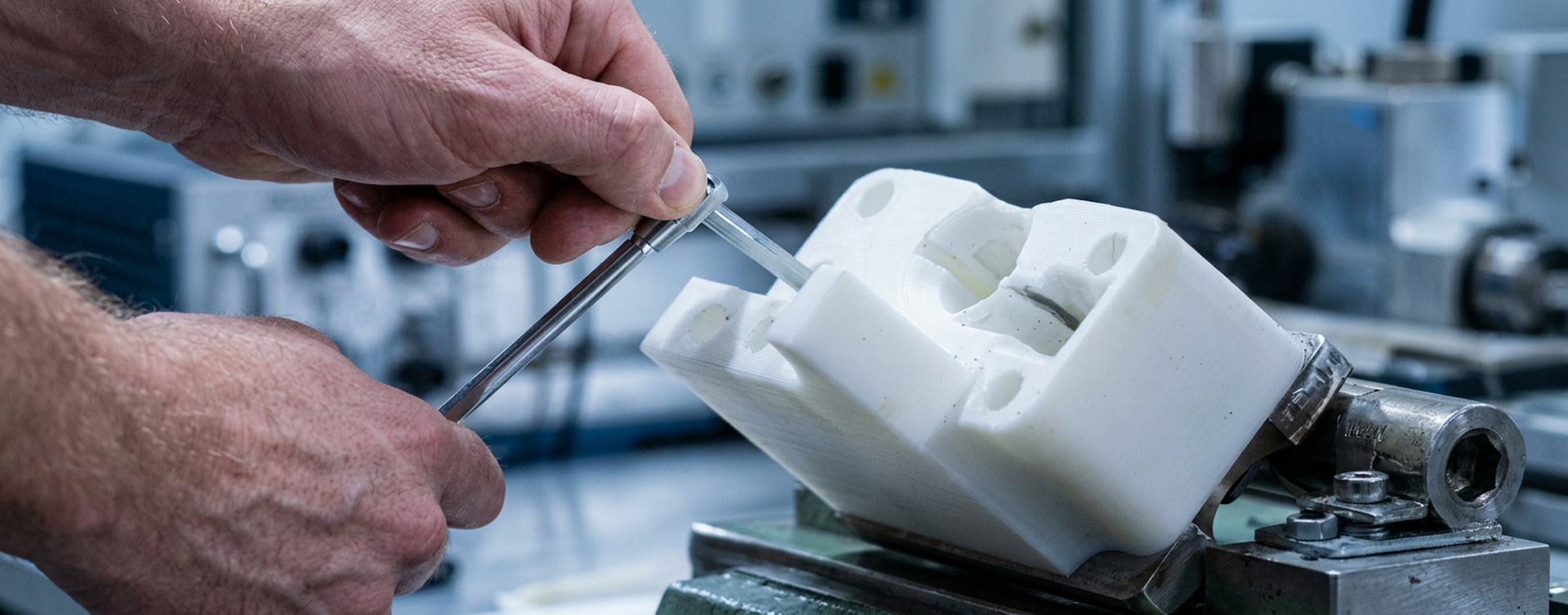
3D printed jigs and fixtures can support assembly, inspection and maintenance when the tool is designed around its working conditions. The important decisions include load direction, material grade, temperature exposure, contact surfaces and the checks required before release to production.
For industrial fused filament fabrication (FFF), a material extrusion process, choosing a polymer is only one part of that work. A carbon-fibre-reinforced fixture and an electrostatic-dissipative assembly tray solve different problems. Each needs its own design and production criteria.
The following five rules provide a practical starting point for evaluating polymer tooling with Omni3D.
1. Define the working conditions for 3D printed jigs and fixtures
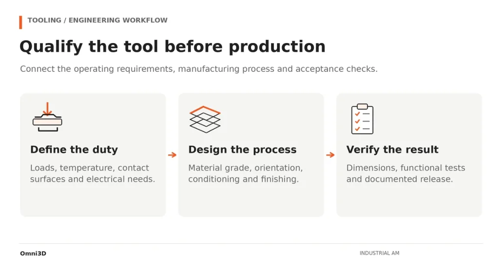
Begin with the operation the tool must perform. Identify what it locates, supports or clamps, then record the forces, contact points and allowable movement. A fixture can remain intact and still be unusable if it deflects enough to move a component out of position.
Document continuous loads separately from short peaks. Include exposure to cleaning agents, oils, heat and repeated handling. For heated operations, record both the temperature and exposure duration rather than relying on a single maximum value.
Use those requirements to shortlist materials from the Omni3D engineering polymer portfolio. CF PA-12 may be a candidate where stiffness and mass are important, while ABS ESD addresses an additional electrical requirement. High-temperature polymers deserve consideration when the operating environment justifies their processing demands.
| Tooling requirement | Design question | Evidence to collect |
|---|---|---|
| Location and alignment | How much movement is acceptable under load? | Deflection and repeatability measurements |
| Repeated clamping | Which areas see cyclic stress or creep? | Representative loading and endurance checks |
| Heat and chemicals | What temperature, duration and fluids are involved? | Grade-specific data and exposure testing |
| Electronic assemblies | How does the fixture fit the ESD control programme? | Relevant electrical measurements on the finished tool |
| Frequent changeovers | Which interfaces wear or require adjustment? | Inspection criteria and replacement procedures |
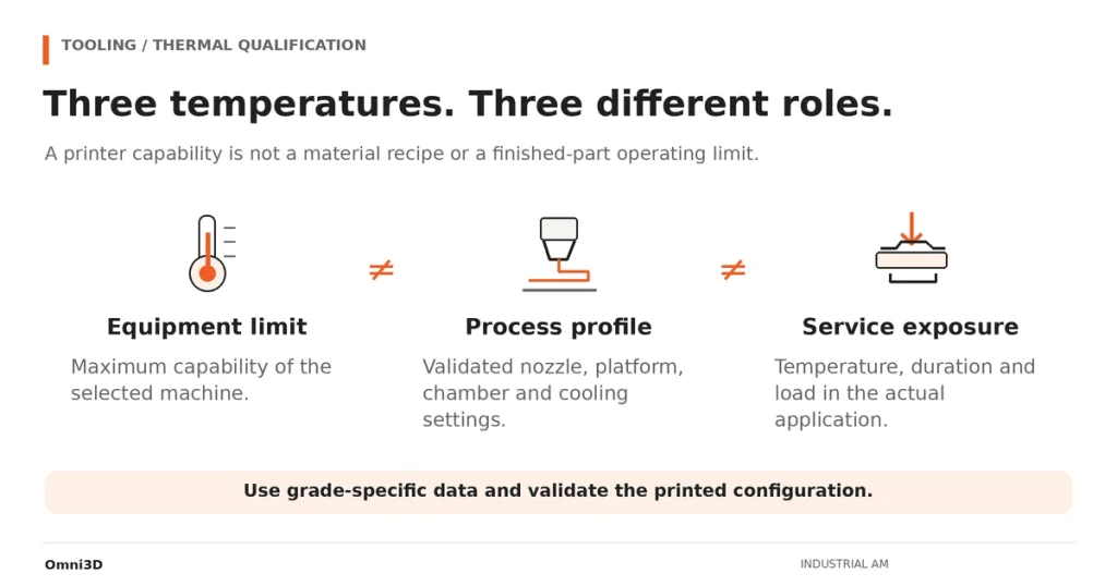
A material datasheet helps screen candidates. Final selection should account for the printed configuration and the actual use of the tool.
2. Design the load path and build orientation together
Layered construction makes orientation an engineering decision. Check how the principal loads act relative to the deposited paths and layer interfaces. Pay particular attention to thin necks, bosses, sharp internal corners and features that carry pull-out loads.
Compare orientations before committing to a build. A position that improves the load path may also increase supports, obscure a locating surface or make finishing more difficult. Choose a balanced configuration and record it as part of the tool definition.
Wall thickness, ribs and local reinforcement should follow the load case. Increasing infill alone is not a substitute for designing the supporting structure. Likewise, a generic percentage reduction in Z-axis strength is not a dependable design value for every polymer and process.
For a production fixture, define the acceptance test before printing. That could include a loaded dimensional check, repeated operation on a representative assembly or an agreed endurance test. The acceptance limits should come from the manufacturing operation.
3. Control material condition and the thermal process
Drying, storage and printing conditions belong in the manufacturing plan. Follow the supplier’s guidance for the exact grade, using suitable drying equipment and a handling method that limits moisture uptake before extrusion.
Research on FFF polycarbonate published by NIST demonstrates that environmental temperature and moisture can affect part geometry and mechanical behaviour. It supports treating the printing environment as a process variable; its results are not a universal temperature recipe for other polymers.
Specify the nozzle, platform and chamber settings as separate parameters. A machine’s maximum chamber temperature describes equipment capability, not the correct setpoint for every filament. Include cooling and removal instructions, particularly for large or dimensionally sensitive tools.
The Omni TECH+ is one platform to evaluate for documented engineering-material combinations such as CF PA-12 and ABS ESD. For a more demanding thermal process, assess the requirements against the relevant system configuration before selecting equipment.
For fibre-filled grades, also confirm that the extrusion hardware is suitable for abrasive material. Record the nozzle configuration and include wear checks in maintenance planning.
4. Use replaceable interfaces where the tool contacts the work
A printed body can be combined with metal or polymer inserts to create a serviceable assembly. Drill bushings, threaded inserts, locating pins and replaceable pads allow the contact function to be designed separately from the main structure.
Plan these interfaces in CAD. Define the insertion or fastening method, available wall thickness, edge distances and final inspection requirements. Where a hole or datum requires machining, specify the finishing operation and leave an allowance appropriate to the process.
Avoid applying the same interference fit or machining allowance to every material. The geometry, printing orientation and installation method all affect how the interface behaves.
This hybrid approach also makes maintenance clearer: replace the worn contact element, inspect its seat and return the tool to service according to an established procedure.
5. Qualify ESD behaviour and release the finished tool
For electronics tooling, assess the completed fixture within the site’s electrostatic discharge (ESD) control programme. A filament designation alone does not establish how the printed, assembled and grounded tool will behave.
The EOS/ESD Association’s guidance on static control explains the importance of grounding, handling practices and appropriate conductive or dissipative materials. Select the applicable test and acceptance criteria with the person responsible for the ESD programme. Surface resistance, resistance to ground and surface resistivity should not be treated as interchangeable measurements.
Record the material batch, print profile, orientation, finishing steps and inspection result. Reassess the tool when a change could affect its function, including a new coating, contact insert or material grade. Applications involving flammable or explosive substances require their own suitability assessment beyond electronics ESD controls.
Evaluate cost per accepted tool
Compare the complete route: design, material preparation, printing, supports, finishing, inserts, inspection and any rejected builds. Include the benefit of a faster engineering change only where it can be measured against the existing operation.
For broader process selection, see Omni3D’s comparison of industrial FFF, CNC machining and injection moulding. An additive route is worth developing when it meets the tool’s functional requirements and offers a credible operational or economic benefit.
Evaluate your tooling project with an Omni3D expert. Share the CAD model, working loads, temperature exposure, material constraints and inspection requirements to define the next qualification step.







