
Industrial automotive 3D printing helps engineering teams check full-scale geometry before committing to tooling, evaluate flexible components and assess selected parts for low-volume production. The value depends on the decision each printed part supports: confirming fit, investigating deformation or qualifying a component for its intended service conditions.
Omni3D projects illustrate these applications through an electric tuk-tuk fender, a flexible mud flap for Vicim and vehicle components developed with Arrinera. Using fused filament fabrication (FFF), a material extrusion process, teams can turn CAD designs into physical parts for evaluation alongside their established manufacturing workflows.
Where industrial automotive 3D printing fits
A prototype, a production tool and an end-use component have different acceptance criteria. Identifying the purpose of the print before choosing the material and process helps keep development focused.
| Application | What the printed part supports | What engineers need to verify |
|---|---|---|
| Full-scale geometry validation | Checking a design before mold manufacture | Dimensions, interfaces, clearances and assembly fit |
| Flexible functional prototyping | Evaluating shape and deformation | Material response, mounting behavior and representative test conditions |
| Small-batch production | Manufacturing selected final components | Service requirements, repeatability, inspection and cost per accepted part |
The strongest starting point is a specific engineering question. Can the cover be installed without interference? Does a flexible element retain the intended shape around its mounting points? Can a low-volume component meet its requirements without dedicated molding tooling?
Validating an electric tuk-tuk fender before mold production
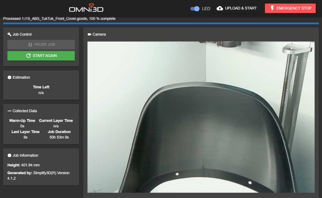
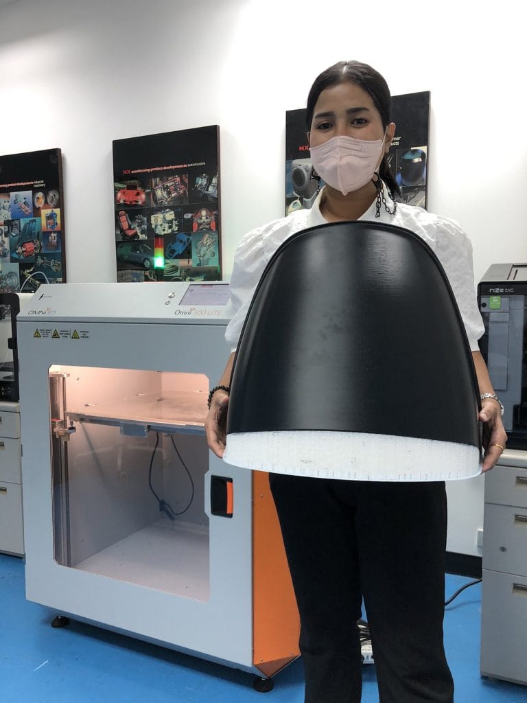
A manufacturer in Thailand working with fiber-composite parts for buses, electric tuk-tuks and other vehicles needed to assess a component physically before committing to mold production. A full-scale prototype gave the team a way to compare the design with the vehicle assembly and check fit beyond the CAD environment.
The project involved an electric tuk-tuk front wheel cover measuring 436 × 391 × 400 mm. The supplied project notes record a 50-hour build using Omni3D large-format printing, with ABS-42 and HIPS-20 listed as the material combination. The notes also specify 25% rectilinear infill and two perimeters.
| Recorded project parameter | Value |
|---|---|
| Component | Electric tuk-tuk front wheel cover |
| Prototype dimensions | 436 × 391 × 400 mm |
| Recorded material combination | ABS-42 / HIPS-20 |
| Infill | 25%, rectilinear |
| Perimeters | 2 |
| Build time | 50 hours |
These figures describe this prototype. The build time is not the complete development lead time: preparation, support removal, inspection and fit checks must also be planned.
The business value was the opportunity to assess the component before investing in the final mold. The supplied customer interview reports easier prototyping and reductions in time and cost, without a numerical comparison. The case demonstrates a practical validation step rather than a guarantee that subsequent tooling will need no changes.
See the related automotive tooling validation case study for the published project overview.
Choosing a current system for large-format work
For manufacturers evaluating a similar workflow today, Omni TECH+ combines a 530 × 500 × 570 mm build volume with an enclosed, actively heated chamber. Its current product page specifies a maximum chamber temperature of 80°C and predefined settings for Omni3D filaments and selected third-party materials.
The build volume supports large components, while chamber control and documented settings provide a basis for process development. Settings still need to suit the geometry, material and required result. A predefined profile does not replace first-part inspection or application testing.
These are current product capabilities, not a reconstruction of the historical tuk-tuk print settings.
Flexible functional prototyping for Vicim
Vicim approached the Omni3D Printroom team with a different requirement: a full-scale prototype of a flexible vehicle mud flap. The project brief called for visual assessment, compatibility with adjacent components and investigation of deformation and forces associated with airflow.
According to the supplied project notes, the team used TPU-93A and an Omni LITE+ industrial 3D printer with a dual-gear filament feed system. The flexible material supported the intended prototype behavior, while controlled filament feeding supported the printing process.
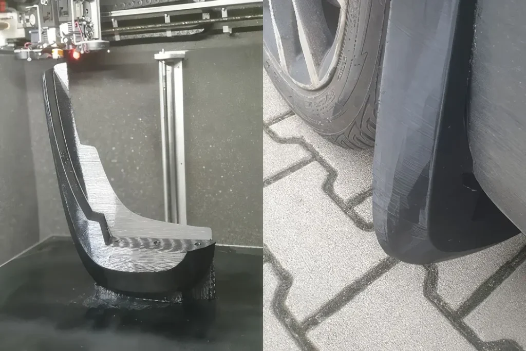
The prototype provided a physical model for reviewing the shape and its interaction with the surrounding assembly. Engineers could revise the design and print another iteration before approving the geometry for subsequent mass production.
The notes identify aerodynamic behavior as an evaluation objective, but do not provide a wind-tunnel procedure, airflow velocity or measured drag result. The engineering lesson is therefore about enabling physical evaluation. A printed TPU prototype should be assessed against its test purpose before its behavior is treated as representative of an injection-molded production component.
Small-batch production and the Arrinera example
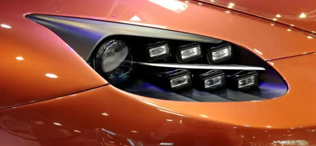
For selected low-volume parts, direct additive manufacturing can also be evaluated as the production route. Avoiding a dedicated mold changes the cost structure, but the decision still depends on quantity, geometry, material, finishing, inspection and the required service life.
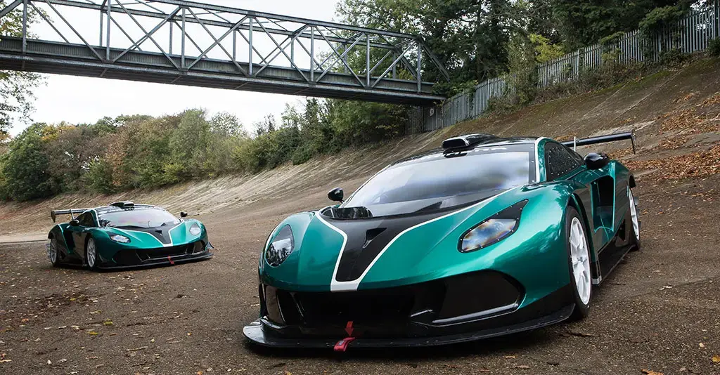
Omni3D’s documented work with Arrinera included full-scale design validation and selected final vehicle parts. The documented applications include a front-light frame and a side-mirror casing. This illustrates how one development program can use printed parts for different purposes, with separate requirements for a prototype and a component intended for installation.
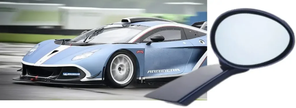
The Omni3D automotive applications page includes the Arrinera case video and further automotive examples.
Compare the complete production route
A useful comparison includes tooling investment, preparation, machine time, materials, labor, finishing and inspection. For a printed batch, it should also account for support material, rejected builds and the capacity available to meet delivery requirements. For a molded batch, tooling maintenance and the expected production quantity affect how the initial investment is distributed.
The relevant measure is the cost per accepted part at the required delivery rate. A low initial tooling cost alone does not establish the most economical process, and a successful prototype does not automatically qualify a production batch.
Define the next validation step
Start with the part’s intended role and a written set of acceptance criteria. Geometry checks need defined dimensions and interfaces. Flexible prototypes need representative deformation and mounting tests. Final components need a validation plan tied to their operating environment and manufacturing process.
Document the CAD revision, material, orientation, print settings and inspection results so the team can connect each outcome to the configuration that produced it. That record helps engineering and production decide whether to revise the design, continue toward conventional tooling or evaluate direct additive manufacturing.
Discuss your automotive application at IMTS 2026
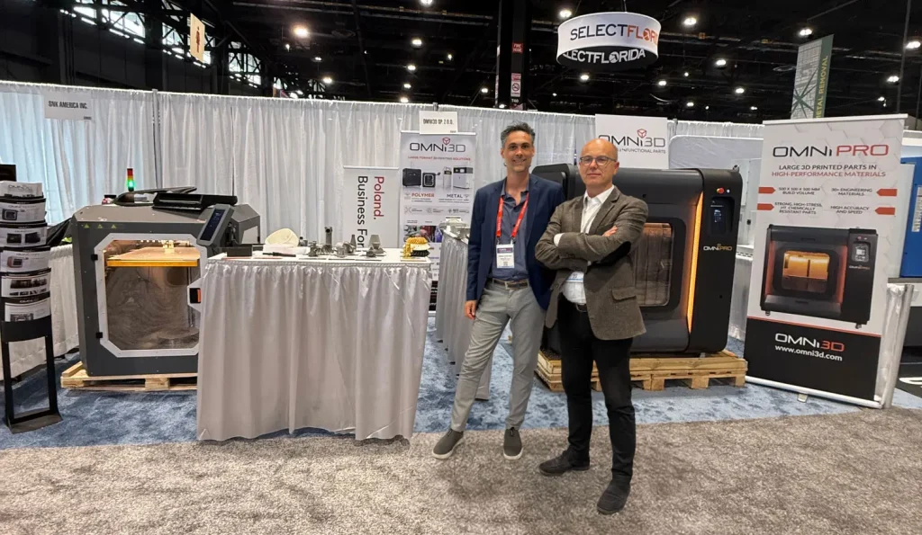
IMTS 2026 takes place September 14–19 at McCormick Place in Chicago. Omni3D’s U.S. office and IMTS announcement identifies the Omni PRO and Omni TECH+ showcase with Build Momentum in the South Building, Level 3, Booth 338591.
Bring a part drawing, target quantity and current manufacturing challenge to discuss where industrial automotive 3D printing could fit your workflow—from full-scale validation to selected production applications.
Evaluate your automotive application with Omni3D. Share the geometry, material requirements, service conditions and current manufacturing method to assess an appropriate printing and validation workflow.







